


Views: 0 Author: Site Editor Publish Time: 2026-09-08 Origin: Site


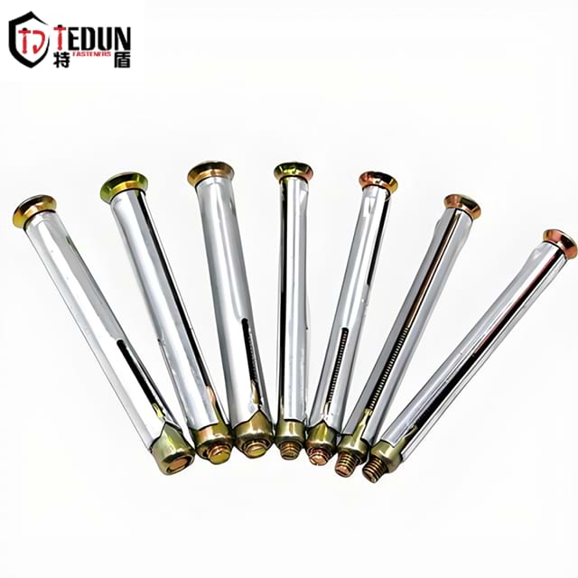
Guessing edge distance requirements is a leading cause of concrete breakout. Engineers and contractors often rely on outdated rules of thumb. This practice introduces immense risk to critical structural connections. Placing an anchor bolt too close to a free edge creates overlapping stress zones. These aggressive stress zones compromise the substrate. They severely risk catastrophic load failure. Edge blowout compromises structural integrity instantly. It inflates project costs and delays construction timelines. You need an evidence-based framework for evaluating edge distance requirements. This guide will help you compare different anchor types. We will explore how to mitigate installation risks effectively. You will learn to navigate specific constraints for various fastening solutions. We will analyze the impact of load direction and substrate conditions. You can protect your installations by mastering these fundamental engineering principles. Proper planning prevents expensive and dangerous structural failures.
Rule of Thumb vs. Reality: While industry standard often dictates a minimum edge distance of 5 to 10 times the anchor diameter, precise requirements depend heavily on anchor type and concrete condition.
Mechanical vs. Chemical: A mechanical anchor bolt requires significantly more edge distance due to radial expansion forces; a chemical anchor bolt can safely be installed closer to the edge.
Code Compliance: Ultimate edge distance validation should always align with ACI 318 (Chapter 17) design standards and manufacturer-specific engineering data.
Stress Cones Matter: Adjacent anchors and edge proximity create overlapping stress cones, reducing the total allowable load capacity of the fastening system.
Structural blowout near a slab edge triggers severe financial consequences. Rework costs escalate quickly when edges fail. Compromised structural integrity demands expensive and time-consuming remediation. Delayed timelines frustrate stakeholders and inflate labor budgets. You cannot afford to guess minimum distances. Precision is entirely mandatory.
Installing fasteners generates intense internal stress. Sustained shear and tension loads compound this baseline stress. Concrete cannot easily absorb outward pressure. Radial stress from installation pushes aggressively against the nearest free edge. Spalling occurs when the concrete surface flakes off. Breakout happens when a large cone of base material fractures away completely. Both failures destroy the connection.
Substrate condition drastically alters edge failure thresholds. Concrete inherently develops micro-fissures over time. Pre-existing cracks near the slab edge weaken the material significantly. Uncracked concrete handles higher radial forces safely. Cracked concrete demands greater edge distances to prevent catastrophic failure. You must always assume concrete will crack unless engineered otherwise.
Common Mistakes in Edge Evaluation:
Ignoring hairline cracks near the intended installation point.
Failing to account for long-term concrete shrinkage.
Assuming all edges share the same structural integrity.
You need foundational metrics to calculate safe distances. These primary variables dictate the size of the internal stress cone. They determine how the load transfers into the substrate. You must gather these metrics before drilling any holes.
Primary Edge Distance Calculation Variables
Variable | Definition | Impact on Edge Distance |
|---|---|---|
Anchor Diameter (d) | The nominal outside width of the fastener. | Larger diameters require significantly greater edge clearance. |
Effective Embedment Depth (hef) | The true depth the fastener reaches inside the concrete. | Deeper embedment creates wider stress cones near the edge. |
Concrete Compressive Strength (psi) | The measure of the substrate's ability to withstand loads. | Lower strength requires larger edge distances to prevent blowout. |
Load direction heavily influences edge constraints. Tension loads pull the fastener straight out. Shear loads push the fastener sideways toward the concrete edge. Shear forces near an edge are particularly dangerous. They require much larger clearances than simple tension loads. You must analyze the primary load vector accurately.
Generic calculators often fail in edge distance planning. You must consult brand-specific technical data. Look for ESR reports from the ICC-ES. Authoritative compliance requires strict alignment with ACI 318 Chapter 17 standards. Manufacturer data always overrides general rules of thumb. Trust engineered data over intuition.
Different fastening mechanisms behave differently near slab edges. We must compare them closely to select the optimal solution. Your choice dictates the required clearance.
A wedge anchor bolt relies on high radial expansion force. It expands outward to grip the concrete tightly. Torquing the nut pulls the wedge up. This action forces the expansion clip against the hole walls. This mechanism creates immense internal pressure.
This category demands the highest edge distance. You typically need 8 to 10 times the anchor diameter. The exact multiple depends on the effective embedment depth. They require this massive buffer to prevent the concrete from blowing out laterally.
Use them strictly for interior slab placements. They excel in applications requiring ample spacing. A standard mechanical anchor bolt handles heavy-duty static loads beautifully. Avoid using them near critical edges.
A chemical anchor bolt cures and bonds directly to the concrete pores. It creates zero expansion stress during installation. The threaded rod simply rests in the adhesive. The epoxy distributes the load evenly across the entire hole depth.
These solutions offer the lowest edge distance requirements. They are ideal for tight margins. The absence of installation stress allows for closer placements. You can safely mount them near slab perimeters.
Choose them for close-to-edge structural mounts. They also perform exceptionally well in cracked concrete. They handle vibrating loads better than friction-based alternatives. Epoxy solutions provide ultimate peace of mind near edges.
A concrete screw uses a unique mechanical interlock. It cuts threads directly into the base material. It avoids heavy outward expansion during installation. Driving the screw creates a secure physical lock.
The required distance remains moderate. It is less than a traditional wedge fastener. However, it generally requires more clearance than an adhesive solution. The thread-cutting action still induces some local stress.
They work best for removable applications. Use them for medium-duty edge fastening tasks. They install quickly and remove easily. They offer a balanced compromise for many structural scenarios.
Real-world installations rarely involve a single fastener in isolation. Multiple variables complicate edge distance planning. You must evaluate the entire structural connection. System-level thinking is critical here.
Every concrete anchor bolt creates a cone of stress inside the substrate. Placing them near an edge is inherently risky. Placing them near another fastener compounds this risk. Overlapping stress cones drastically reduce the total allowable load capacity. The concrete cannot support the combined forces. You must space fasteners adequately to separate their stress cones.
Mounting steel base plates near slab edges presents specific challenges. These structural plates often group multiple fasteners closely together. Custom engineering calculations become an absolute necessity. Engineers use specialized design software to distribute shear loads properly. You must balance spacing and edge constraints simultaneously. Standard tables cannot resolve complex base plate interactions.
Hitting rebar near structural edges is a frequent implementation reality. Rebar strikes impact your planned drill depth. They force you to alter the fastener placement. Repositioning a hole might push you too close to the edge. You must scan the concrete before drilling. Avoiding these costly conflicts saves time and money.
Best Practices for Advanced Applications:
Always utilize Ground Penetrating Radar (GPR) near edges.
Use PROFIS or similar software to model overlapping stress zones.
Design base plates with slotted holes to allow minor field adjustments.
Choosing the right system requires evaluating multiple factors simultaneously. You must balance structural needs against physical constraints. Follow a logical decision path.
If your available edge distance exceeds 10 times the diameter, proceed normally. A standard mechanical fastener is typically safe. It is also highly cost-effective. You can torque it down without fearing immediate breakout.
If your available edge distance is less than 5 times the diameter, pivot immediately. Default to adhesive solutions. They eliminate expansion stress entirely. This choice protects the concrete margin from fracturing under load.
Site conditions can restrict your options severely. Temperature affects adhesive curing times significantly. Cold weather delays the chemical bonding process. Wet holes might compromise the adhesive entirely. You must assess these environmental factors before specifying a chemical solution. Sometimes, environmental constraints force a complete structural redesign.
Project managers must demand ICC-ES evaluation reports. Require these documents for any specified fastener. This practice ensures authoritative code compliance. It protects your structural liability. Never approve unrated hardware for edge applications. Your due diligence prevents catastrophic field failures.
Edge distance is never a static number. It remains a dynamic calculation based on several interacting factors. You must account for the fastener mechanism. Concrete integrity and load direction also dictate your final placement. Protect your margins by following these final takeaways.
Always verify minimum distances against ACI 318 Chapter 17 standards.
Transition to chemical bonding when operating near minimum distance thresholds.
Eliminate radial expansion forces whenever spacing becomes incredibly tight.
Consult a licensed structural engineer when base plates require overlapping components.
Scan slabs for rebar to avoid last-minute edge proximity conflicts.
A: The standard baseline is 5 to 10 times the anchor diameter. However, this is only a general guideline. Load types and anchor mechanisms always supersede rules of thumb. You must consult specific engineering data to ensure safe installations.
A: It poses a high risk of blowout. These fasteners create massive expansion forces. You must strictly adhere to the minimum distances listed on the manufacturer spec sheet. Failing to do so usually causes immediate concrete spalling.
A: Drilling too close creates micro-fractures in the substrate. Applying torque or structural load to the fastener expands these fractures. This leads to immediate or delayed spalling. The concrete will eventually break out completely under stress.
A: They are vastly superior for tight edges. They generate zero expansion force during installation. However, they are not perfect for every scenario. You must carefully manage curing times, hole cleanliness, and environmental temperature constraints.
A: Deeper embedment creates a significantly larger internal stress cone. A larger stress cone interacts more aggressively with the nearby concrete edge. Therefore, deeper installations generally require greater edge distances to prevent lateral breakout under heavy loads.