


| Quantity: | |
|---|---|


Core Structure And Components
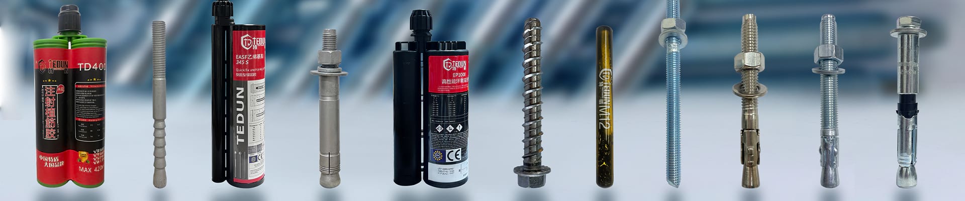
1. Two-Tube Structure: This is the origin of its name. It primarily consists of an inner tube (core shaft/expansion mandrel) and an outer tube (undercutting sleeve/expansion sleeve), which are precisely matched. The outer tube typically features pre-designed weak points or cutouts.
2. Other Standard Components: Include a threaded rod (stud), flat washer, spring washer, and nut. These components are used for load transfer and providing clamping force.
"Self-Undercutting" Principle - The Key to Mechanical Interlock:
This is the most crucial innovation of this anchor type. During installation, no special undercutting drill bit is required to pre-form an undercut at the base of the hole.
When torque is applied to tighten the nut, the threaded rod pulls the inner tube upwards.
The specific geometry of the inner tube (e.g., conical head) interacts with the inner wall of the outer tube, forcing the lower part of the outer tube (at the pre-designed weak zone) to undergo radial expansion and simultaneous controlled deformation (typically splitting or flanging) within the substrate at the base of the hole.
This expansion and deformation process directly "cuts into" and displaces the surrounding substrate at the bottom of the drilled hole, forming a mechanical interlock cavity that closely conforms to the shape of the expanded anchor section.
Ultimately, the expanded section of the outer tube forms a powerful mechanical interlock (keying effect) with the substrate at the base of the hole. This interlock is the primary source of the anchor's pull-out resistance. It functions similarly to a "barb" or "wedge" securely locked within the substrate.
Advantage
1. Exceptional Load-Bearing Performance:
The formed bottom mechanical interlock provides extremely high pull-out resistance and shear resistance. This makes it particularly suitable for heavy-duty and dynamic load environments (vibration, shock). Its load-bearing capacity typically far exceeds that of conventional expansion anchors.
2. Superior Seismic (Earthquake) and Fatigue Resistance:
The mechanical interlock delivers stable anchorage. It exhibits minimal susceptibility to loosening or failure under cyclic loading or vibration, making it a preferred choice for seismic design.
3. Broad Substrate Compatibility:
Non-Cracked Concrete: Standard application.
Cracked Concrete: The keying effect maintains effective anchoring force even during crack opening and closing (requires compliance with relevant certification standards, e.g., ETAG 001 Annex C).
Natural Stone: Provides reliable anchorage (note: stone type and compressive strength must be considered).
4. Simple and Efficient Installation:
Eliminates the need for special undercutting drill bits and the undercutting step, simplifying the installation process.
Requires no curing or hardening time after installation (unlike chemical anchors), allowing for immediate loading or proceeding with subsequent construction activities. This significantly enhances construction efficiency and project timelines.
5. High Reliability:
Mechanical locking performance is stable and less susceptible to environmental factors (e.g., temperature, humidity).
6. Controlled Installation:
Installation is torque-controlled, enabling easy quality monitoring.
Application
1. Steel Structure-to-Concrete Base Connections
Critical Applications: Column bases, structural brackets, truss supports, seismic bracing frames.
Value Proposition: Provides high-tension capacity and shear resistance essential for transferring heavy structural loads. Its immediate load-bearing capability accelerates steel erection sequences, while vibration resistance ensures long-term integrity in dynamic structures (e.g., industrial floors, mezzanines).
2. Heavy Machinery & Equipment Anchorage
Examples: Generators, turbines, CNC machines, presses, large-scale HVAC units, process piping supports.
Value Proposition: Excels under high static loads, operational vibrations, and potential impact forces. Eliminates curing delays (vs. chemical anchors), allowing immediate equipment commissioning. Its fatigue resistance prevents loosening in continuous-operation environments.
3. Critical Connections in Large-Scale Infrastructure
Structures: Bridges (bearings, expansion joints), power plants, stadiums, airport terminals, high-rise cores.
Value Proposition: Meets rigorous seismic performance requirements (e.g., AISC 341, EN 1998) due to stable mechanical interlock in cracked concrete. Enables rapid installation of prefabricated elements during tight construction schedules.
4. Facade & Wind-Load Critical Systems
Applications: Curtain wall mullion anchors, sunshade supports, large signage, cantilevered canopies.
Value Proposition: Superior resistance to wind-induced cyclic loading prevents progressive failure. Reliable performance in cracked concrete accommodates building movement. Compatibility with thin elements (e.g., stone panels) via controlled expansion.
5. Transportation & Energy Infrastructure
Rail: Track fastenings (e.g., slab track), overhead catenary (OCS) mast foundations, signal gantries.
Energy: Wind turbine tower baseplates, transformer anchorage, substation equipment.
Value Proposition: Corrosion-resistant options (e.g., A4 stainless steel) suit harsh environments. High dynamic load capacity ensures safety under train-induced vibrations or turbine harmonics. Certified for safety-critical applications per standards like ETA, ICC-ES.
6. Natural Stone & Masonry Anchorage
Uses: Stone cladding fixings, monument bases, pre-cast stone elements, heritage restoration.
Value Proposition: Controlled expansion mechanism minimizes splitting risk in sensitive materials. Provides reliable tension capacity where adhesive anchors may fail due to moisture/contamination. Requires substrate verification (e.g., compressive strength > 30 MPa).


